Bandpass Filter in Continuous Time in C
Definition: A bandpass filter (BPF) is an electronic circuit that passes a certain band of frequency without attenuation. The particular band of frequency passes by the filter is known as passband.
The important parameters that have to be considered in a BPF are the low and high cut-off frequency, centre frequency along with bandwidth and selectivity.
Bandpass filters are basically of two types: Active BPF and Passive BPF.
An active bandpass filter requires an external power supply and consists of active components like IC, op-amp, transistor. Although, a passive bandpass filter does not need an external power source and is comprised of only passive components that include a capacitor, inductor etc.
Basically, wireless transmission requires BPF in order to restrict the bandwidth of the signal. This is done for accurate data transmission along with high speed.
Block diagram of Bandpass filter
The figure below shows the block diagram of BPF formed by the cascade connection of low pass filter(LPF) and high pass filter (HPF).
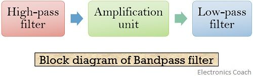
The section consists of an LPF, HPF along with an amplification unit. Such a combination of LPF and HPF will provide us bandpass filter.
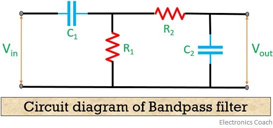
Let us move further and have a look at the circuit diagram of a BPF
LPF basically passes the lower frequency band and completely suppresses the frequency band above the cut-off frequency.
On the contrary, HPF passes the frequency that falls above the cut-off frequency and eliminates the lower band of frequency.
Thus, by cascading the two different filters, we can have a circuit that passes the band whose frequency is neither too low nor too high.
Generally, bandpass filters are termed as second-order filters due to the presence of 2 reactive components in their circuits. It basically provides difference lower and high cut-off frequency.
Bandpass filter frequency response curve
The characteristic of the BPF is shown by the frequency response curve given below:
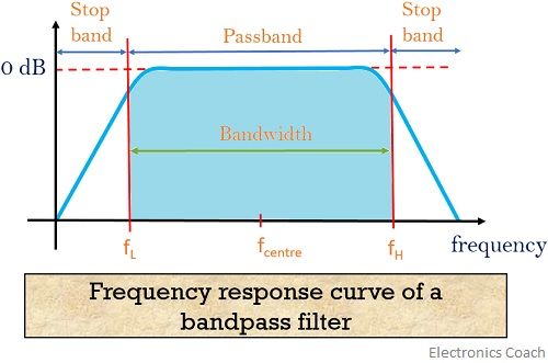
Here we have noticed that the filter has 2 cut-off frequencies i.e., lower cut-off frequency (fL) and upper cut-off frequency (fH). The difference between the two is the frequency band that is passed via BPF whose bandwidth is given by
BW = fH – fL
For a BPF, fH and fL can be formed by using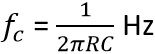
Let us now consider an example to determine the cut-off frequency and bandwidth of the bandpass filter.
Suppose, R1 = R2 = 10kΩ,
C1 = 0.1 µF and
C2 = 0.0025 µF
So higher cut-off frequency will be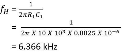
and lower cut-off frequency is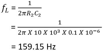
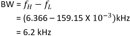
As we have already discussed the bandwidth is the difference between the two cut-off frequency. So,
It is to be noted here that beyond the two cut-off frequency, the roll-off is 20 dB/decade. The centre frequency of the BPF is given by the geometric mean of the two cut-off frequencies
The expression for centre frequency is given as![]()
When we talk about an ideal bandpass filter then it is automatically assumed that it will possess a flat passband characteristic. This simply means, that the filter completely passes only the desired passband and rejects the other frequency bands.
But, practically no such ideal filter exists. This is so because a complete rejection of the frequency outside the passband is not accomplished by the filter. This is known as roll-off characteristic of a filter and is expressed in terms of dB.
Phase response of BPF
The figure here shows the phase response of the BPF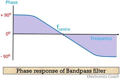
As we can see here, that at 0 frequency, output leads the input by 90⁰. However, a gradual decrease in phase difference is noticed while we move towards the centre frequency.
Any further movement away from the centre frequency will cause the output to lag the input.
A passive filter works as an attenuator thus it provides an output signal having the amplitude less as compared with the input signal. However, to have a distortionless signal at the output, some amplification measures must be considered while designing the circuitry.
Advantages
- It allows narrow to wide passband along with stinging selectivity.
- BPF provides stability and reliability together.
- Its low cost and small size make it suitable for various applications.
- SNR and sensitivity of the receiver are also enhanced with the help of bandpass filtering approach.
Applications of Bandpass filter
Wireless transmission and reception system use bandpass filters during signal transmission. In the transmitter section, it limits the signal thus preventing it from interference with other systems.
Similarly, in the receiver section, BPF only selects the particular passband and rejects other. Astronomy and atmospheric science also find uses of bandpass filters.
cessnadreatenty60.blogspot.com
Source: https://electronicscoach.com/bandpass-filter.html
0 Response to "Bandpass Filter in Continuous Time in C"
Post a Comment